In the previous article, “Overview of Parts Drawing Disassembly (Part 1),” we introduced the basic concepts of disassembly as well as key points from both design and manufacturing perspectives.
Parts drawing disassembly is not simply the task of cutting out individual components from an assembly drawing. Rather, it is an important process for creating accurate and easy-to-understand drawings while considering machining methods and assembly procedures.
In this Part 2, we will take a more practical look at the standards and procedures used when carrying out parts drawing disassembly, along with detailed notes to keep in mind during the drawing process. We have summarized practical points that are useful on the job site, so designers and disassembly engineers are encouraged to use this as a reference.
Now, let’s go step by step through the specific processes and checkpoints of parts drawing disassembly.
4. Basic Standards Based on the Overview of Parts Drawing Disassembly
-
Standards for threaded holes, circular holes, stepped holes, and tapered holes
In drawing creation, follow the “Thread Standards” defined in the Technical Standards.
-
Other standard parts
During the disassembly process, follow the Standard Parts List defined in the Technical Standards.
5. Procedures for Parts Drawing Disassembly
5.1 Disassembly of Parts Drawings from Assembly Drawings
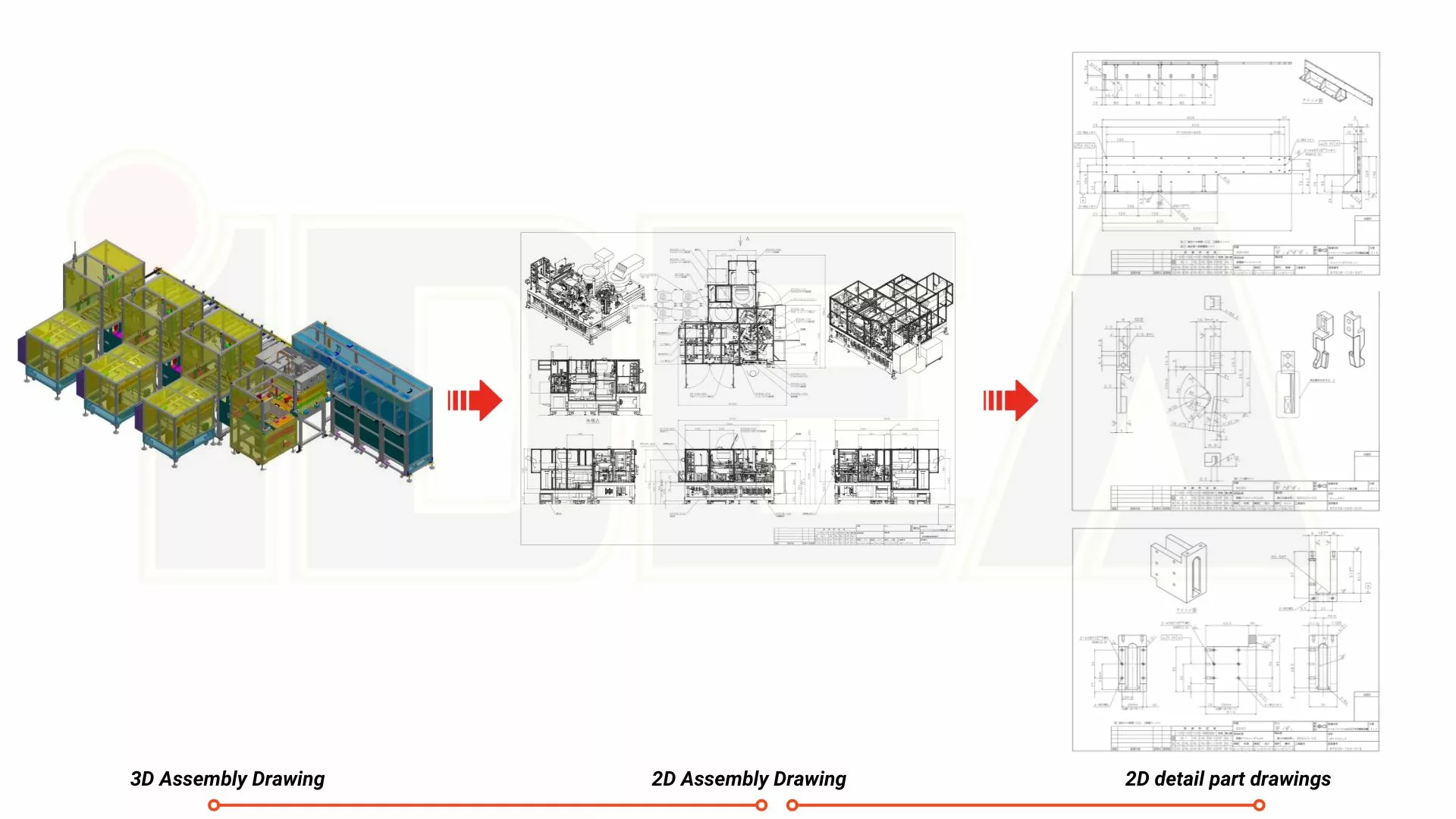
Disassembly from 2D Assembly Drawings
When using 2D design software such as AutoCAD, ICAD, or CADSUPER, individual parts are separated from the projection views of the assembly drawing.
This method can be time-consuming and difficult to interpret. However, if some components are stored as “Blocks,” the disassembly process becomes easier.
When performing disassembly from 2D assembly drawings, it is easy for dimensions to become distorted or omitted. In particular, if “standard parts (commercial products, purchased items)” are included, it is essential to check the product specifications to confirm details such as thread pitch and mounting hole positions accurately.
Disassembly from 3D Assembly Drawings
When using 3D design software such as SolidWorks or Inventor, parts disassembly is carried out directly from the 3D model.
With this method, deformations in shape can be visually confirmed, resulting in higher accuracy and shorter working time compared to 2D methods.
For more details, please refer to our 2D/3D disassembly services.
5.2 Selection of Drawing Frames and Scales
In some cases, the drawing frame or scale to be used may be specified in advance by the customer. In such cases, follow the instructions and adjust only the scale if necessary.
If no specifications are provided regarding drawing frames or scales, the designer selects an appropriate frame and scale based on the size and content of the part. It is important to ensure that the final printed drawing is clear and easy to understand.
Since scale standards may differ depending on the customer, any specified scale must always be followed. If there are no specific instructions, refer to the following priority scales when selecting.
Preferred Scale
| Full Scale | 1:1 |
| Enlarged Scale | 10:1 5:1 2:1 |
| Reduced Scale | 1:2 1:3 1:5 1:10 1:20 1:50 1:100 |
Not Recommended Scale
| Enlarged Scale | 3:1 |
| Reduced Scale | 1:4 1:6 1:8 1:12 1:15 1:30 1:40 1:60 1:1,5 1:2,5 |
5.3 Checking Part Specifications
Before starting the disassembly process, the following items must be checked:
-
Function of the part (e.g., rotating part, fixed part)
-
Type of part (shaft, bushing, base plate, bracket, frame, welded part, etc.)
-
Assembly method (fixed mounting, mounting onto another part)
-
Material
-
Machining method, surface roughness
-
Heat treatment
-
Surface treatment
5.4 Dimensioning, Hole Machining Instructions, and Other Notes
Before adding dimensions to a part drawing, it is necessary to clearly define the machining reference.
This machining reference usually coincides with the dimension origin (datum point). Setting this reference correctly is extremely important—choosing the wrong reference can lead to inaccurate machining and, in the worst case, assembly failures. (If there is any uncertainty about the reference, be sure to confirm it.)
Since dimensioning rules differ by customer, any special instructions provided must always be followed.
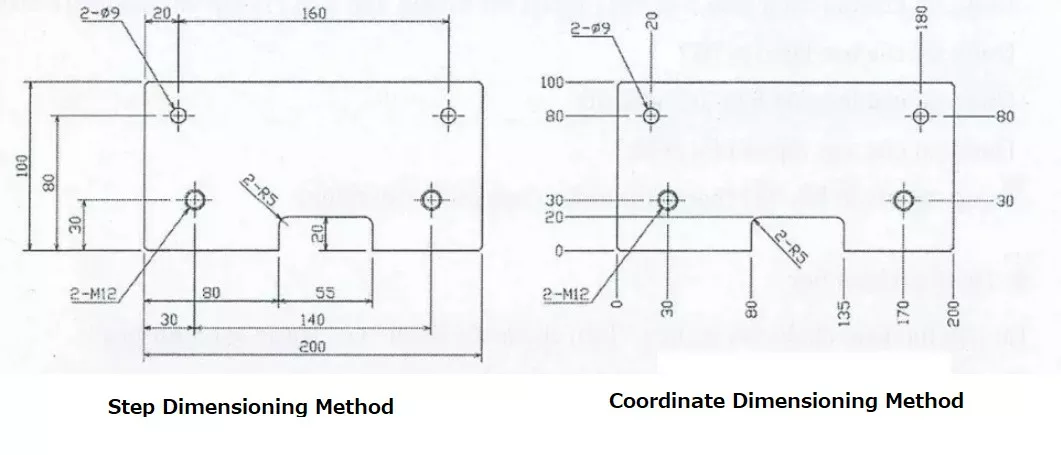
In general, there are two common dimensioning methods:
- Step Dimensioning Method
Dimensions are recorded sequentially for shapes or machining areas that share the same function. This is the most widely used method. - Coordinate Dimensioning Method
Used by a smaller number of customers, but it is very suitable for customers who perform CNC machining. This method makes it easier to directly apply dimensions to machining programs.
Exceptional Cases
- For small parts or parts with relatively few dimensions, the Step Dimensioning Method is more appropriate.
- On the other hand, for parts with a very large number of dimensions, such as large base plates, the Coordinate Dimensioning Method is more efficient.
Basic Procedure for Dimensioning
1. Record the overall dimensions.
2. For welded parts, record the material dimensions before welding and the mounting positions of each plate.
3. Record machined shape dimensions (excluding pin holes and bolt holes).
4. Record the dimensions of each hole:
Clearly indicate hole diameter and hole type (pin hole, bolt hole).
When necessary, also specify special notes such as: Hole depth; Punching instructions; Bushing press-fit instructions; Back-side machining instructions; Chamfering instructions (C-chamfer, R-radius, etc.)
5. Record the fillet and chamfer dimensions.
Precautions When Dimensioning
- For a given shape or machining feature, always record all required dimensions in one step (X-axis dimensions, Y-axis dimensions, shape dimensions, depth dimensions, etc.).
- Do not duplicate dimensions (dimension duplication is prohibited).
- Arrange dimension lines in a clear and easy-to-read layout. Always keep in mind the perspective of the machinist, and prepare drawings that are easy to understand for actual processing work.
5.5 Setting Dimensional Tolerances
There are two types of tolerances:
- Dimensional tolerances
- Geometric tolerances
5.5.1 About Dimensional Tolerances
All machining dimensions indicated on drawings inherently have tolerances. In particular, dimensions without explicitly specified tolerances are applied according to JIS standard tolerances. On the other hand, for dimensions that require special tolerances outside of the standard, these must be specified individually on the drawing.
JIS Standard Tolerances
- Dimensions without specified tolerances shall follow the JIS tolerance tables.
- However, for dimensions 0.5 mm or smaller, appropriate tolerances should be set individually depending on machining requirements and part functionality.
Types of Tolerances
The types of tolerances may vary depending on the standards specified by each customer. In general, it is common practice to apply “m-class” tolerances for machining dimensions, and “c-class” tolerances for raw material cutting dimensions.
Special Tolerances
For dimensions that require special tolerances, they must always be specified on the drawing. The specific values are determined based on the function of the part and the required accuracy, and may also be designated as customer specifications. In addition, some tolerances are defined as industry standards, such as the following:
Examples of representative special tolerances
-
Tolerance for distance between two pin holes (excluding slot holes): ±0.02 mm
-
Bearing bush hole tolerance: H7
-
Bearing shaft outer diameter tolerance: h7 or g6
-
Fit tolerance between shaft and hole: H7/h7
-
Pin hole tolerance: H7 (unless otherwise specified)
5.5.2 About Geometric Tolerances
For detailed instructions on geometric tolerances, refer to the “Geometric Tolerance Standards” in the Technical Standards.
For some parts and critical dimensions, it is necessary to specify geometric tolerances such as position and parallelism. Examples include:
-
Mounting areas for cylinders, LM guides, and robo-cylinders require high-precision parallelism tolerances.
-
Shaft-type parts require tolerances for coaxiality and straightness.
-
Plate surfaces may require flatness tolerances.

5.6 Indication of Surface Roughness

Indication of Surface Roughness
There are two types of surface roughness indications:
-
Indication by triangular symbols
-
Indication by Ra or Rz (unit: µm)
Standards for Surface Roughness
-
For functional surfaces that come into direct contact with the product, very high surface roughness is required. In this case, the standard is ▽▽▽ (equivalent to Ra 1.6).
-
For joint surfaces where parts are assembled together, the standard surface roughness is ▽▽.
-
For machined surfaces that do not contribute to assembly or are of lower importance (e.g., cover mounting surfaces, sensor bracket mounting surfaces), the standard is ▽ (equivalent to Ra 25–Ra 12.5).
Notes
When indicating surface roughness using Ra, always specify the Ra value correctly, and do not mirror (invert) the symbol.
5.7 Welding Instructions
There are two main types of welding instructions:
-
Indication of welding position
-
Indication by welding symbols
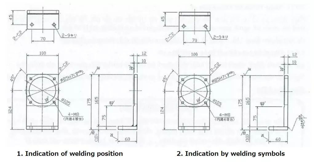
Sometimes, both of the above two types may be used together.
For details regarding welding symbols, please refer to the Technical Standards – “Standards for Indicating Welding Symbols.”
Note
Welding symbols must not be mirrored (inverted) when indicated.
5.8 Indication of Surface Treatments (Plating, Coating, etc.)
Depending on the material of the part, various surface treatment methods may be selected. Instructions for surface treatment are basically based on the customer’s specifications.
- Generally, parts made of iron or aluminum are given surface treatments after machining to prevent rust or oxidation.
- On the other hand, stainless-steel parts usually do not require any special surface treatment.
5.9 Indication of Heat Treatment
Parts subject to impact, sliding parts, or components that frequently come into contact with the product require heat treatment to enhance durability and wear resistance. The details of heat treatment are also, in principle, based on the customer’s specifications.
5.10 Other Notes
In addition to the above instructions, the following types of notes may also be indicated on the drawings:
-
Example: “Unless otherwise specified, chamfer corners C0.3–C0.5,” or “Unless otherwise specified, bending radius R shall be R1.”
These instructions are primarily based on the customer’s design standards.
5.11 Input of Title Block Information
The title block should include the following information:
- Machine name
- Unit name
- Part number
- Part name
- Material
- Quantity
- Designer
- Drafter
- Approver
- Date
- Information on heat treatment and surface treatment
In some cases, certain customers may require that this information be entered using dedicated macro tools.
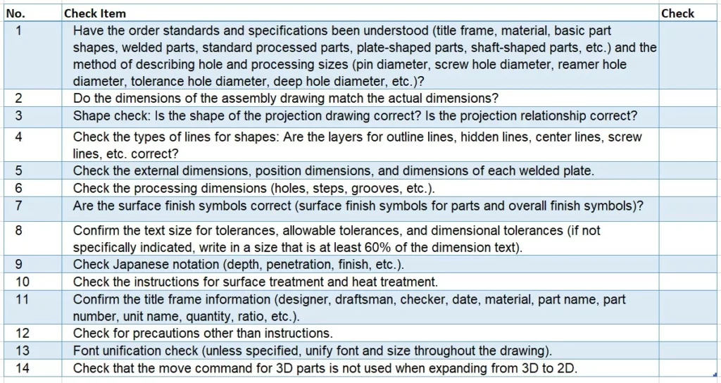
5.12 Final Check of the Entire Drawing
After the work is completed, the disassembly drafter must always check the entire drawing. It is necessary to confirm that no information is missing. In addition to the customer-specified checklist items, confirmation is generally carried out based on the company’s internal checklist, as shown below.
5.13 Establishing the Process for Part Drawing Separation
The previous sections explained the necessary tasks when performing part drawing separation. However, identifying the most efficient and accurate method to create drawings is also a critical point.
To smoothly proceed with part separation, it is essential to establish a clear process. The separation process refers to a systematic workflow that organizes each step into a structured procedure. By following the sequence step by step, omissions and mistakes can be prevented.
After confirming the detailed information of the parts, understanding any deformations, and completing the disassembly work, the procedure for separation is determined. This procedure can be organized mentally, but it is highly recommended to write it down on paper whenever possible. Although it may take some time at first, once you become familiar with it, both speed and accuracy will improve.
Basic Steps of Separation
- Selection of drawing frame and arrangement of parts
- Processing of deformations and organization of line types
- Addition of sectional or projection views (as necessary)
- Entry of external dimensions and addition of surface roughness symbols (as necessary)
- Entry of machining dimensions, tolerances, and surface roughness (as necessary)
- Entry of hole dimensions, tolerances, notes, and surface treatment instructions (as necessary)
- Input of information into the drawing frame
- Addition of notes outside the drawing frame (as necessary)
- Final check (based on checklist)
It is important to flexibly adjust the above steps depending on the type and complexity of the parts. Furthermore, by standardizing the workflow, consistent operations can be achieved, enabling efficient and accurate separation.
Importance of Establishing the Separation Process
If there is no clear separation procedure, hesitation and decision-making errors are more likely to occur during work. Constantly asking, “How should this part be handled?” will slow down the process, increase mistakes, and reduce productivity. Therefore, it is crucial to establish the optimal separation procedure to ensure an efficient workflow.
For further details, please also refer to “Overview of Part Drawing Separation (Part 1).”
