What is electronic gearbox of servo?
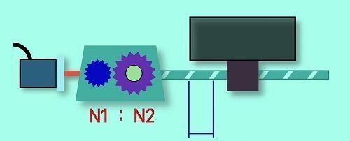
When using a servo motor, it is often used in conjunction with a servo reducer or sprocket or transmitted through a belt to the actuators, resulting in the transmission ratio from the motor shaft to the actuator will have to go through a ratio if this ratio combined with the encoder resolution of the servo motor is odd, it leads to an odd number of pulse generators, which makes it difficult to calculate the number of pulses.
Therefore, servo manufacturers often integrate into their drivers an electronic gearbox to make calculating the number of pulses more convenient. For example, due to the mechanical mechanism, if you want to turn 1 turn, you must send 3600 pulses, the electronic gearbox has the ability to adjust to 1000 pulses per turn to be more convenient for programming PLC because even numbers are more convenient for the calculation. In fact, when programming the servo control, the result must change according to the hardware’s parameters, so if the number of pulses on the ring is odd, when multiplying and dividing, it will create cumulative errors, causing system errors big.
How to calculate actual electronic gearbox for servo motor?
Manufacturers often use a set of electronic gearbox parameters that is a fraction that includes the numerator and denominator of the form A/B. This means that when you send X pulses, the servo motor will run X x A/B number of pulses.
For example:
The servo motor has an encoder resolution of 2500 pulses/rev, so if you want to generate 1000 pulses, the motor output should rotate 1 revolution, how much should the gearbox be set?
We can apply the following formula: 1000 x A/B=2500.
In which 1000 is the actual number of pulses for the motor to rotate 1 revolution, 2500 is the resolution of the servo motor. So A/B=2500/1000=5/2.
So we set the electronic gearbox with the numerator 5 and the denominator 2. Usually we have to shorten A/B in a minimalist form to make it easier to set.
Note: When installing an electronic gearbox for servo motors, you need to set this ratio within the manufacturer’s allowable threshold. If set outside this threshold may cause the driver to error or accelerate suddenly, resulting in the servo motor will no longer run correctly. Therefore, when using a PLC to generate pulses to control servos, you should choose a servo with an appropriate resolution, if you choose a type that is too high, it will be difficult for you to program.
If your servo system uses a reducer or ball screw, then you apply the above formula to these mechanical mechanisms based on their ratio coefficients to be able to have easier-to-use units in the system during servo control programming process.
Therefore, to install the electronic gearbox correctly, you must determine the following parameters:
- How many encoder pulses when the motor turns 1 revolution?
- What is the desired number of pulses to the servo for the motor shaft to rotate 1 revolution?
From there we can choose the parameters A and B of the electronic gearbox.
Hopefully the sharing of IDEA is useful for everyone in choosing parameters for electronic gearboxes in their projects.
If you need to design and build an automation system, please contact us immediately:
- Email: Sales@ideatechmart.com
- Website: ideagroupvn.com