
Part drawing separation is a crucial step in mechanical design, where assembly drawings are broken down into detailed part drawings for manufacturing. This process ensures accuracy, functionality, and compliance with client standards. In this article, we’ll cover the basics and key principles to perform Barashi effectively.
1. Definition of part drawing separation
To manufacture a machine, device, or production line, the process must go through several key stages. The first stage is the idea of design → Assembly drawing drafting (2D or 3D) → Detailed drawing drafting (also known as Part drawing separation) → Processing → Assembly → Inspection → Packaging → Application.
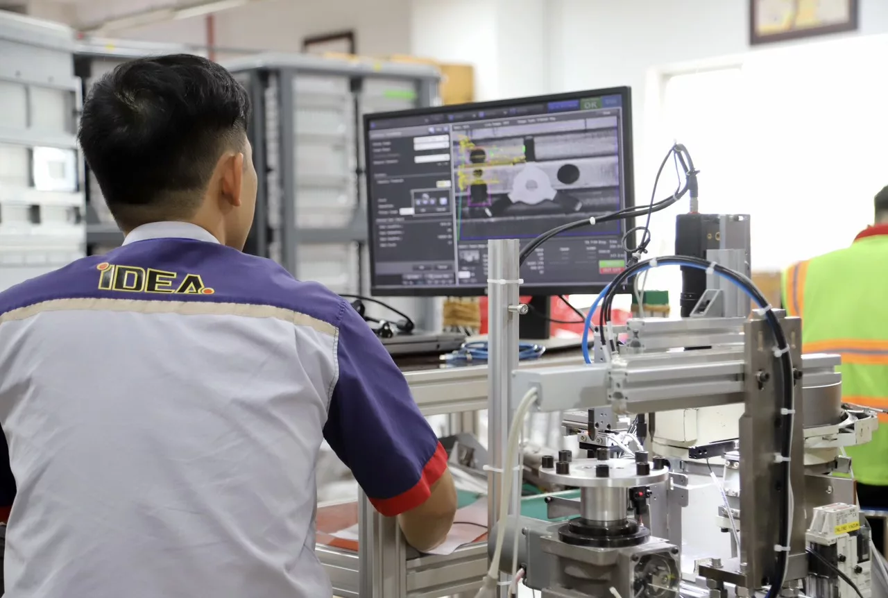
 1") The designers at IDEA Group are working on part drawing disassembly tasks
The designers at IDEA Group are working on part drawing disassembly tasks
The work of separating parts from a 2D or 3D assembly drawing into a new drawing frame, recording all dimensions, tolerances, treatment methods, symbols, … into a complete detailed drawing. This work is called part drawing separation or barashi (Japanese).
Thus, part drawing separation is very important. This work is referred to as detailed design. Detailed drawings after being separated will be forwarded to processing division. The quality, accuracy and workability of the part depends greatly on the accuracy of the detailed drawing, for example:
- The parts can not be assembled if their sizes are wrong.
- Unreasonable tolerances may make the parts fail to fit in.
- Unreasonable roughness of the parts may affect the working ability of the part and cause the products made by this machine to be defective and poor quality.
- Other influencing factors.
2. Basic knowledge to know before barashi
* Materials of parts: The most commonly used materials are carbon steel, SUS, aluminum alloy (collectively referred to as aluminum material), plastic materials such as POM, MC Nilon, PET, etc. There are also some other kinds of materials.
3. Barashi tutorial
3.1 Client’s standards
When carrying out any work on an order, the first thing to do is to carefully read the standard. Understand all the content in the client’s standards.
3.2 Drawing frame (Template)
Barashi is required to have a drawing frame, before barashi, if the drawing frame is not available, you must ask the Project Manager to provide a drawing frame.
For 3D design software such as SoliWorks, Inventor, Catia, Creo, etc. when changing the drawing frame, drawing scale will be changed automatically, so it is quite easy for the properties to be automatically changed accordingly.
For 2D design software such as Autocad, Icad, BricsCad, … when changing the drawing, the drawing scale will not be changed automatically (except for pre-installed modules), you have to replace it yourself. Some properties will also be immutable, which requires special attention. When changed, all properties must be adjusted to match the current drawing frame.
3.3. Standard layer rules of a part drawing
Each client usually has a separate rule about the layer and when working must comply with the layer that they have specified. Normally, for 3D design software, the layer is pre-set, when the barashi automatically change, just use the correct template provided by the client. As for 2D design software, the client’s layer rules must be followed.
Layer standards for each order will vary, depending on the clients. Basically there are the following types of layers:
- Outer contour layer: bold solid line (out line), thickness is usually from 0.25~0.3mm.
- Layer of hidden lines: dashed lines, thickness is usually from 0.18~0.2mm.
- Centerline layer: dotted line (centerline), thickness is usually 0.13~0.15mm.
- Dimension line layer: has the same thickness as the hidden line. This layer is also used for text notes.
- Solid line: Used for lace outline or indicator for partial cut, break cut. The thickness is usually equal to the thickness of the centerline.
- Double dotted line: used for reference lines, the thickness is equal to the centerline.
- Some other layer types.
Note: For Icad software, the line thickness is divided into 3 types: large thickness, medium thickness, small thickness. If there is no instruction from the client, we only use 2 types: medium thickness and small thickness. The medium thickness is used for the outer contour, the rest is used for the small thickness.
3.4. Projection angle, projection layout and dimension origin
Projection angle
Different from the Vietnamese standard, the projection angle according to the JIS standard is from the 3rd projection origin.
 2")
Layout of Projections in Drawings
Order of priority from ① to ⑤
Usually in barashi drawings and even assembly drawings, the views are arranged mainly from ① to ② (Main view ①, flat view, right side view)
In addition to the projection layout rules as shown above, there are other layout rules such as:
- According to the directions arranged in the assembly drawing.
- According to processing rules.
 3")
When arranging the projection on the drawing, depending on which case we choose accordingly. The resulting drawings must be easy to read, understand and avoid causing confusion.
Rules for the layout of some basic parts
The cylindrical part is arranged horizontally, the processed part is on the right side. (Arranged according to processing rules)
 4")
Parts with long form are arranged horizontally.
 5")
Other types of parts.
Frame: Layout according to the actual working direction. The bottom is the ground side.
 6")
Bracket
 7")
Basic standards
- Standards for threaded holes, smooth holes, step holes, and taper holes.
- Standard for other accessories.
In the next article, we will explore step-by-step instructions for performing Barashi effectively. Stay tuned!