Working principle of hydraulic system
In a hydraulic mechanism, the fluid for the contacting surfaces and for the transmission of the force is used. The fluid will be circulated inside a closed recirculation system thanks to the hydraulic pump and controls.
When the electric or diesel engine rotates the pump, the hydraulic fluid in the fluid tank will be compressed and pushed to other components in the hydraulic system. Fluid pressure will be controlled by the relief valve. It helps the equipment operate safely and maintain durability.
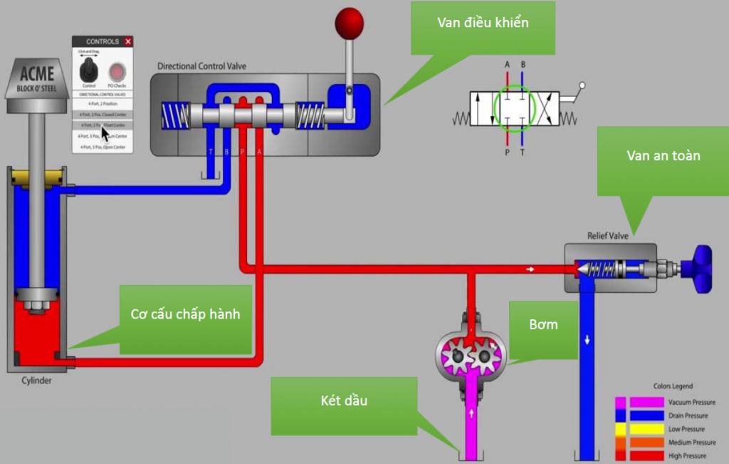
At this time, hydraulic fluid is brought to the actuator by the flow and pressure generated by the hydraulic pump. From there, the rotary or reciprocating motion in the actuator will be operated. After transferring energy, hydraulic oil will be passed through the radiator and returned to the storage tank, continuing a new energy transmission cycle.
Structure of hydraulic leveling system
The basic hydraulic leveling system requires 3 main parts to ensure safety factors as follows: Hydraulic system, hydraulic frame and lifting table. Each part has its own function, ensuring the lifting and lowering operations are smooth and safe.
The hydraulic system consists of the following basic components:
- Hydraulic motor: This component is usually imported from abroad, has the main function of converting kinetic energy into mechanical energy, performing reciprocating motion.
- Cylinder: This is the most important component in the leveling mechanism, the cylinder size is changed flexibly to suit the desired load. There are two types of cylinders – single cylinder and double cylinder.
- Distribution valve: It can change the flow branch at the nodes of the pipeline and only allow the flow to move in a certain pipeline. Therefore, the hydraulic leveling can operate stably and the hydraulic lifting process takes place according to the settings. The distribution valve is made up of 3 main parts: valve body, electromagnet and slider.
- Control valve: this vavle is the place where most of the nodes are concentrated in the pipelines of fluid circulation.
Applications of hydraulic system
- Industrial Application: Industrial application of hydraulics is controlled by the mechanism known as electrohydraulics. The main advantages of this are fast response and precision. Some of the examples of industrial hydraulics are textile industry machinery, presses, loaders, crushers, automated production lines, machine tool industry…
- Repair Application: In garages and motorcycle service centers, there are many equipment using hydraulic lifting mechanism such as car lifts, motorcycle lift tables, ….
In the AGV self-propelled vehicle at IDEA, the hydraulic lifting system is applied to the pallet lifting mechanism of the IGR-PTA series and the lifting table system of the IGR-AMR series.
RECENT POSTS: